Ask Patrick

Q: If I have an isolating valve at the geyser, what else should I keep in mind?
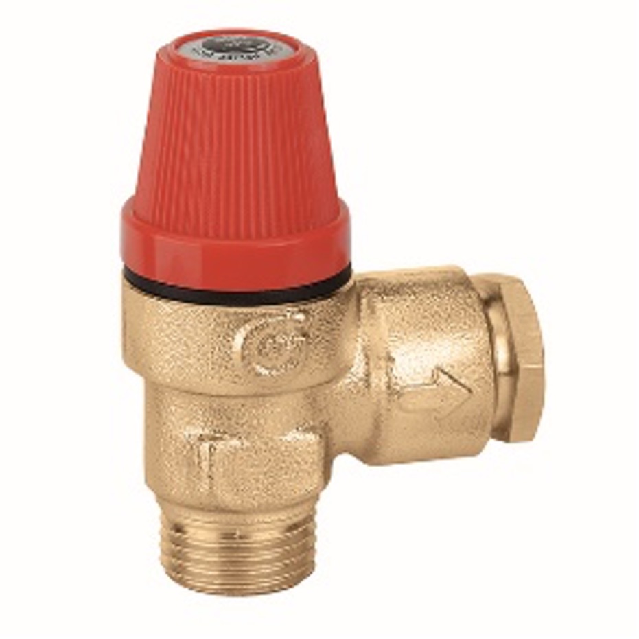
A: There is a basic rule that must be kept in mind with all geyser installations. You are not allowed to have an isolating valve between the geyser and the Pressure Relief Valve. In most installations that have been correctly plumbed for balanced pressure the Pressure Reducing Valve and the Pressure Relief valve is situated outside the building to facilitate ease of installation. If an isolating valve is now placed near the geyser, this would cut off the path of relief for the geyser. This installation would not comply to SANS 10254.
How could I keep the installation as is but make it compliant? This is done easier that what you would think. All you must do is to fit a Pressure Relief Valve between the geyser and the isolating valve. Just remember that this valve must be fitted over the geyser tray and must be piped out according to the rules set out in SANS 10254.
10254.
Q: Must all installations have balanced water?
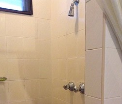
A: SANS 10254 says that the water pressure SHALL be balanced at all mixing points. Most installation these days has at least one if not more points where the water is mixed before leaving the final outlet. You may say, “I don’t have any mixers in the installation”. But ask yourself, is there a shower installed? Even though you have two separate stop taps the water is still connected via a “T piece” before reaching the terminal point namely the shower rose. This is thus a mixer and the water must be the same dynamic pressure at the hot and cold water stop taps.
So only installations where there is no shower and only separate pillar and bib taps throughout the whole installation may be unbalanced
However, it is still recommended that you always plum for balanced pressure to all terminal points as you do not know when a DIY person may change the taps at a basin to a mixer.
.
Q: How can I see if the water pressure is balanced?
A: it is not always easy to just see if the system has balanced pressure. The best way is to use a pressure gauge and to physically check the pressure at he taps. If you do not have a pressure gauge you could open the taps (hot and cold) fully and see if the flow is the same for both. This method could be very messy with water splashing everywhere and is not always accurate as there may be other restrictions in the line that is causing a reduced flow.
Q: Are you allowed to install a Pressure Control Valve upside down?
A: This is a question that is often asked and may be a bone of contention. If you only look at the at the physical operation of the valve, there is not up or down, and the valve will operate at any angle. However, that is not all that has to be kept in mind when the installation is done. SANS 10254 explicitly states: 5.2 Discharge from valves The discharge pipes from expansion control and safety valves shall c) be so installed that 1) they incline downwards continuously to their outlet, 2) drainage of both valve and piping is ensured, 3) blockage due to freezing or foreign objects is prevented, So, keeping this in mind the expansion valve must be so positioned that it inclines downwards and that drainage of both the valve and the piping is ensured. Each manufacturer has a different valve configuration and installation features that must be kept in mind so that complete drainage of the valve and the piping is ensured. To summarize, no valve has an up or down, but the position is determined by the relief outlet of each valve.
Q: Does my valve stop being SABS compliant if I service it? Will I lose my warrantee?
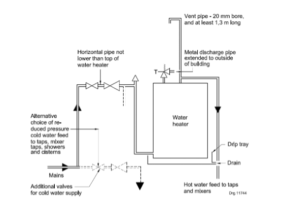
When the main water supply to the house was in the form of a heater tank which provided the dwelling with some pressure, all that was necessary was to have the vertical pipe that stood slightly higher than the supply tank on the cold-water side. Alternatively if the tank was on the roof, the pipe would have to be routed back into the top of the tank. This mechanism acted as a expansion relief valve as well as a vacuum breaker. As soon as negative pressure applied to the inlet all the water would be pulled from this riser pipe and allow air to be sucked in. In summary, it created a combination expansion relief and vacuum breaker. Limitations to this system were that there was little pressure in the Hot Water Cylinder which led to the demand for a closed pressure system.
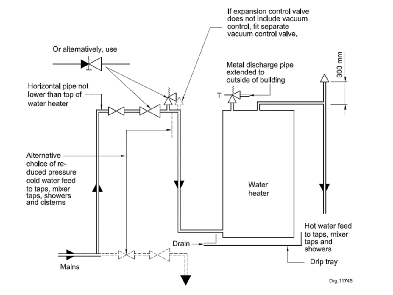
Many will remember the old Latco “Flying Saucer”. Here you could have higher mains pressure and reduce the hot water pressure for an unbalanced installation. Remember in the old days we mainly used single taps and watering can shower roses so balanced pressure was not an issue. You could either have a high pipe, like in the previous type of installation, or use the Latco Relief valve. So where is the Vacuum Breaker now? Few people realize that the Latco relief valve served a dual purpose and that it was a relief valve and a vacuum breaker. A very effective one I might add. So, from the inception of the pressure system, we have been using two vacuum breakers and until we can find a better way of doing these functions, we must continue to do so. Let us look forward to the progress in technology.
Q: Why is it now required to install two Vacuum Breakers when it was never a requirement before?
A: Due to Vacuum Breakers sometimes failing and causing damage we often look for ways to minimize the risk. But let us have a look at some old types of installations.
.
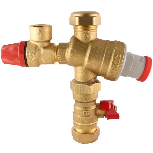
A: How did the product, Valve, become SABS compliant? The manufacturer has designed and produced a product that complies to the minimum requirements set out by SABS Standards. They have also, hopefully, considered what the customers demand from such a product. Because of inhouse and external monitoring we already know what to expect when we buy this product. But how can we be sure that when we are finished working on the valve our expectations will still be met?
We need to start with the basics and make sure that we fully understand the operating principles and performance specifications from the product. The easiest way to achieve this is to attend the training sessions that are offered by all reputable manufacturers. Not only can they teach you how the product works but also on how to maintain its integrity.
The only way to make sure of future performance, and to get the manufacturers backing is to use the genuine replacement parts offered by the manufacturers. Some items may be sealed and unserviceable to ensure that its integrity is maintained. Become a specialist in the services that you offer, and you will get all the support that you need from the knowledge base that is present in the industry.
Once again if you do not know ask.
Q: Why does my Pressure Control Valve not deliver the pressure that it is rated at?
A: Before we answer that question let us consider the functions of the valve. The valve has two main functions:
1) The valve will reduce the mains pressure to the desired system pressure. Normally the lowest maximum acceptable pressure of the components used in a system.
2)
The valve will also relieve any excess build-up of pressure for what ever reason. Typical would be due to the heating of the Hot Water Cylinder.
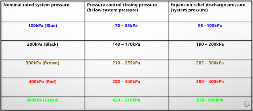
When you first measure the set pressure of the valve you will see that the pressure will always be lower than what it is rated at. A 100kPa valve will only deliver pressure to the value of 70-85kPa.This allows for a certain amount of build-up of pressure before the valve comes to the second function the relieving of excess pressure when it reaches 95-100kPa. If this were not the case the valve would constantly be opening for expansion. These mentioned values can be used as a percentage for the other pressure ratings of the valves. For instance, a 400kPa valve will have a set pressure of 280-340kPa and a relief pressure of 380-400kPa.
All the control valves in the system are related in the differences of their pressures so that there is a uniformity in the level of safety that they provide. Do not tamper with the settings of a valve by placing coins etc. on the spring as this will destroy the engineered safety that is built into every unit. When presented with a problem in an installation contact the manufacturer before you make any modifications.
Remember it is not Knowledge that is power but how we apply that knowledge that makes us strong.
Q: Is a RPZ valve a type of pressure reducing valve?
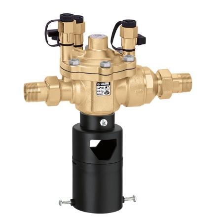
A: This question is easy to answer, and the answer is NO. But what is a RPZ valve then and where should it be installed?
RPZ is the acronym for “Reduced Pressure Zone” Backflow preventer and can be likened to a double non-return valve with extra features.
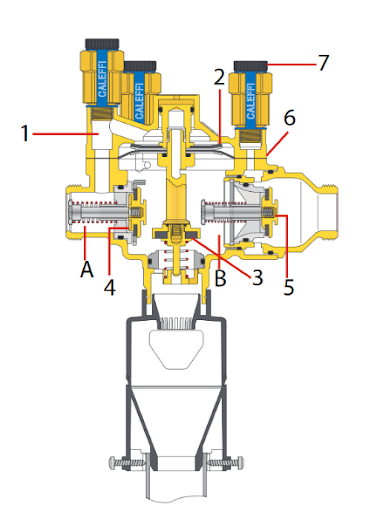
The Valve is divided into three basic areas A, B and C.
A is the inlet port and is separated from the rest of the valve by the check valve (4) and the diaphragm (2). As the pressure builds up on top of the diaphragm it moves the spindle down and closes port (3). As more pressure builds up it will open the check valve (4) and fill area B. Once area B is sufficiently pressurized check valve (5) will be opened and the water will flow into area C.
If the water supply at A fails, the pressure will drop, and diaphragm (2) will no longer keep area B closed. This will result in the water in area B being discharged and because there is no more pressure to keep check valve (5) open it will close and prevent any backflow of water from area C.
But you may ask why we need such an elaborate system to prevent backflow. Will a normal non-return valve not suffice? A plain single or even double non-return would prevent water from flowing back, however if they fail due to dirt being trapped on the seat, and that often happens, the non-return will fail, and we would not know about it until the damage is already done. With a RPZ valve there is a visual indication of the failure and you will immediately be able to give the problem your attention.
A RPZ valve ensures that NO possible contaminated water can enter into the municipal supply as all backflows will be discharged to the atmosphere via the discharge port (3).
The gauge ports (7) make it easy to check the integrity of the unit with the aid of a simple Pressure Gauge.
For more information contact your supplier for installation and fault-finding training or watch this space for the fault-finding article.
Q: Is it necessary when replacing a geyser to replace all the valves?
A: This answer is not just a straightforward Yes/No scenario. When replacing the geyser, we need to first ascertain why the geyser failed in the first place. It could very well be that the geyser failed due to a malfunctioning control valve.
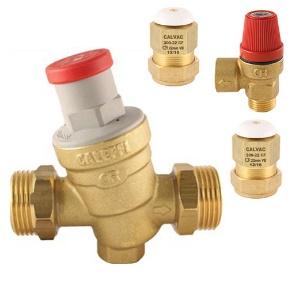
To start off we need to understand what the function is of each component in the system. We have dealt with that in some of the previous articles but feel free to contact your manufacturer for detailed information.
Secondly, we need to make sure that the control valves are performing according to the desired manufactured specifications. This would mean that you would need to know what the previous point entails and that you have the appropriate equipment to perform the necessary tests.
If you have any doubt about the integrity of a control valve it would be prudent to service it or to replace it.
If all the control valves are found to be in good order they can be re-used. The important part is to make sure that your installation complies to the latest version of SANS 10254. (I include an extract)
4.3 Operation of the system
4.3.1 General
4.3.1.1 New installations
All the components of the system shall be installed in such a manner and position as to ensure
a) the safe and effective operation (both mechanical and electrical) of the system and of each
individual component part,
b) the easy, effective and correct removal and replacement of component parts or spare parts
during maintenance, replacement or repair, and
c) the effective discharge and drainage of water from the system.
NOTE Particular attention is drawn to the future replacement of anodes, heating elements, thermostats and
safety valves on closed type water heaters, and due allowance should be made to ensure such correct
replacement.
NB: If you do not know ask. It is preferrable to be ignorant in the eyes of someone else than to endanger the lives of others.
Q: I have a 400kPa valve but the pressure reading on my gauge is only 300kPa. Is the valve faulty?
Q: I have a 400kPa valve but the pressure reading on my gauge is only 300kPa. Is the valve faulty?

By having the valve set pressure a little lower that the system pressure it allows for some expansion to take place without any water being purged. The set pressure vs relief pressure is calculated to a fixed ratio. (see the chart below)
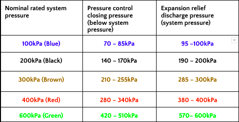
From studying the chart, you will notice that, if you check the system pressure on a 400kPa installation the gauge reading can be anywhere between 280kPa and 400kPa, depending where in the heating cycle it is, and be completely within specifications.
Feel free to contact your valve manufacturer for more information on valve fault finding or look out for a future article on this topic.
Q: What is backflow and how must we protect against it?
A: Movement of any substance in any direction is called flow. So why the term backflow when water moves from an installation towards the municipal potable supply? Firstly, it is assumed that the water in any installation originates from the municipal supply and so the water that flows back towards there is viewed as flowing back and thus called “Backflow”.
In most instances this would be the case, so why would we need to guard against it? What has happened to the water that makes it un-safe to return it from where it comes? Firstly, we need to take cognisance of the fact that once the water passes past the water meter it now becomes the responsibility of the homeowner and the municipality no longer has control over what happens to it. Once they have lost control over what happens to the water, they do not want to let it back into the municipal system.
We could let the water back into the municipal system if we had it tested and certified as SANS 241 quality compliant, but we know that that is not practical. What do we do to the water that could be viewed as contaminating it?
•We often have water softeners on the supply to the home and this is done by adding chemicals to the water.
•The water is often heated in an aged Hot Water Cylinder that will add lime scale to the potable water in a backflow situation.
• When summer comes and we are filling the pool and fishponds with a hose this could also be a cause of contamination.
So, if we look at it from their view the probability of getting contaminants from domestic installations is very high and we have not even ventured into water from alternative sources such as boreholes and rainwater harvesting. Thus, it is no wonder that SANS10252/1 of 2018 says in D.1.1 Design, installation, and maintenance.
All water supply systems shall be designed, installed, and maintained to prevent contaminants from being introduced into the potable water supply system.
The big question now is not the quality of our water but how to prevent it from happening. The regulations are very clear on what is expected from us and how to achieve zero backflow from entering the potable system.
In terms of the National Regulations, SANS10252 -1 (water supply installations for buildings) refer to 7.4 of SANS 10252-1 ‘Preservation of Water and Water Quality’. Reduced Pressure Zone Back Flow Preventers must be installed in any installation where there is a risk of contaminated water or harmful substances being back syphoned or flowing back into a potable water supply line. The regulations state that Back-flow Preventers shall be installed in certain types of installations and buildings, for example:
Medical treatment of people and animals, pharmaceutical or chemical research and manufacturing, dairies, nurseries, stadiums, abattoirs, combined fire systems etc.

By having the valve set pressure a little lower that the system pressure it allows for some expansion to take place without any water being purged. The set pressure vs relief pressure is calculated to a fixed ratio. (see the chart below)

Most of the municipal bylaws underpin this by stating that it is the responsibility of the Homeowner (Not the tenant) to have this maintained once a year. A record must be kept of when this maintenance was done and by whom. The unit must be overhauled or replaced every five years and record of this must also be kept.
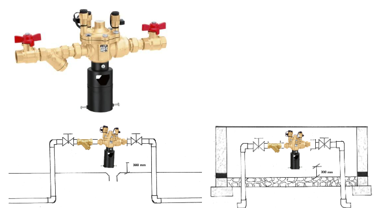
A national regulation requires that any Backflow Preventer discharges where it is visible so that any malfunction of the system can be readily detected and attended to. This means that we cannot hide this valve somewhere in a duct or a manhole, it must be above ground level where the discharge is visible. If theft is a factor the valve may be closed with a surround, but the discharge must still be where it is visible. Below is a drawing of a typical installation.
How does the valve work?
There is a mechanical check valve at the inlet and outlet of the valve. In the middle there is an area (Zone) that is open to the atmosphere. As soon as water pressure enters the valve a diaphragm is pushed down, and the relief port is closed. Once this area is now filled with water the second check valve is opened and the downstream plumbing system can be filled with water.
Q: Why is my geyser valve leaking?
A:One of the biggest complaints received by Geyser Valve Manufacturers is that the vale is leaking. There are many reasons why the valve is discharging water and some of them includes the actual correct function of the valve. To understand why the valve is leaking we must understand what the function of the valve is. The first function is to reduce incoming municipal water pressure to and acceptable level. The chosen system pressure is calculated by analysing all the components in the system and ascertaining what the maximum allowed pressure of each component is. As discussed in a previous article the set pressure of the valve is always lower than the rated pressure. The second function of the valve is to prevent the system from being over pressurized. This excess pressure could be due to expansion, back pressure or a multitude of system errors. The relief of the extra pressure normally occurs at the rated pressure of the valve. So, the first reason for a valve “leaking” is the most obvious one. The hot water cylinder has been heating the water during the normal operation of the system. This has caused the expansion of the water in the cylinder and resulted in a build-up of pressure. The relief valve then opens to rid the system of the extra pressure. The installation is not consuming water at this time and the reading on the water meter will not indicate any flow because of this. In simple terms the water has become more than what it was. To prevent this discharge from irritating the homeowner the discharge of the relief valve should be piped to a convenient place that is still visible but not irritating. This discharge of the valve is a normal occurrence and no cause for concern. The next reason could be that the main seat, that shuts off the incoming pressure when the system has reached the desired operating pressure, could be malfunctioning and the pressure is going straight to the relief scenario. You will be able to identify this problem by using a pressure gauge and checking what the system pressure is without expansion taking place. Most valve manufacturers have spares available and you should be able to repair the valve without removing it from the installation. There could also just be some debris that is lodged on the seat that is preventing it from closing. By cleaning the main seat area, you can remove the obstruction and have the valve fully operational again. A common cause for dirt on the main seat is unbalanced installations that cause debris from entering the valve from the downstream side of the valve. There is no strainer on that side of the valve to prevent this from happening. It is often claimed that the system has worked like this for many years so why is it a problem now? With the system ageing limescale builds up in shower roses and aerators and this causes the miss match of the pressure to be more accentuated. By cleaning the limescale in the system you can alleviate the problem for a while but, it does not solve the problem. To correct the situation the pressure must be balanced to all mixing points. By doing proper fault finding before working on the system, the correct cause of the problem can be found and illuminated. This will illuminate the unnecessary replacement of the valve. So how much water should the valve leak?
Q:Does Legionella really affect us in our daily lives?
Q:Just to recap. What is legionella or also known as Legionnaires’ disease?
A:I have attached an extract copy of the definition from an article published by the SaNTHNet dated Friday, 06 October 2017 07:32:
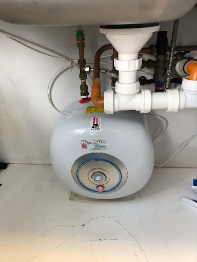
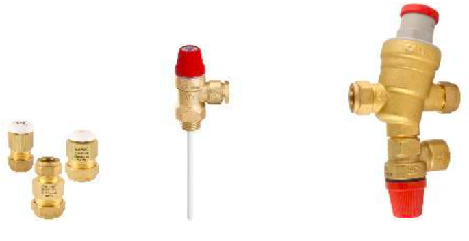
In many cases the installer has tried to make the installation compliant by adding these ancillary valves but always ending with a non-compliant installation.
So, does that mean that we should not use these units? NO, they are great for installations that have a user point that is far from a normal hot water supply.
How do we then make this installation compliant?
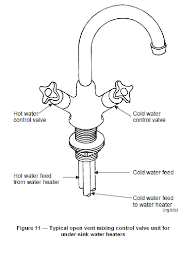
All pictures are not my own but taken from the internet and SANS 10254.
Q:How should my Under Basin Geyser be installed?
A: I have attached an extract copy of the definition from an article published by the SaNTHNet dated Friday, 06 October 2017 07:32:

Legionnaires’ disease is recognised worldwide as an important cause of both community- and hospital- acquired pneumonia. It is caused by Gram-negative bacilli of the Legionella genus. The mortality rate in infected individuals ranges between 10 – 20%. It was named after a large outbreak in 1976 that occurred at a meeting of the American legion, which affected 221 people, causing 34 deaths. Legionella bacteria are common and can be found naturally in environmental water sources, including rivers, lakes, natural pools, and moist soil. Water temperatures in the range of 20°C to 50°C favour growth of the organism. Legionella pneumophila serogroup 1 is the most important species of Legionella that causes disease in humans, although other species can occasionally cause disease. Legionella spp. may also cause Pontiac fever, a mild, self-limiting flu-like illness.
Who can get Legionnaires’ disease?
Any person can develop Legionnaire’s disease. However, the risk is higher in persons over the age of 50 years. Male gender, persons with immunodeficiency syndromes or chronic underlying medical conditions of the lung, heart or liver and smokers are also at increased risk.
Where does Legionnaires’ disease occur in South Africa?
Legionnaires’ disease Legionnaire’s disease may manifest as sporadic cases, small clusters, or outbreaks of disease that can involve hundreds of cases. It is also an important cause of travel-related illness, and may be acquired on cruise ships, in hotels and resorts. In South Africa, both sporadic cases and outbreaks of Legionnaires’ disease have been described. Serological testing identified that approximately 8% of community acquired pneumonias are caused by Legionella species. Prospective surveillance identified 21/1805 (1.2%) cases of legionellosis amongst persons with severe respiratory illness However, due to difficulties in diagnosis and lack of awareness of the disease, very few cases are diagnosed in SA at present. It is very likely that sporadic cases, clusters and even outbreaks occur and are missed.
How is Legionnaire’s disease transmitted?
Persons become infected by breathing in water droplets containing the Legionella bacteria. Water droplets are generated by spraying or bubbling air through water in which the bacteria are present. Human-to-human transmission of Legionella has never been documented. The incubation period for Legionnaires’ disease is 2 – 10 days. Wherever water droplets can be created there is a risk of infection, including:
•Hot and cold-water systems (e.g., showers and taps)
•Cooling towers and evaporative condensers of air conditioners
•
Spa baths (Jacuzzis) and whirlpool baths and natural pools or thermal springs
•
Turkish baths and saunas
•
Ornamental fountains (particularly indoors) and sprinklers
•
Humidified food display cabinets
•
Respiratory therapy equipment
How can Legionnaires’ disease be prevented?
The proper design, maintenance and temperature of potable water systems are the most important method for preventing the amplification of Legionella. Hot water should be maintained above 60˚C and delivered to taps at temperatures above 50˚C. Cold water should be maintained below 20˚C. Plumbing systems should be flushed regularly, and low flow areas eliminated. There are currently no vaccines to prevent Legionnaire’s disease.
As can be seen from the above information we are all at risk. Especially when summer is coming, and restaurants are once again starting to use those misting systems that have been lying dormant and sitting in the sun giving it plenty of time to breed those lovely and willing Legionella bacteria.
Most sports/gym facilities also use circulating blended hot water kept at a constant 38-42℃. This temperature range is a good safe temperature to prevent scolding of any user but, it is also the ideal breading temperature for any Legionella spores present in the circulatory system. Any instance that uses a circulatory blended water supply should do regular maintenance. This would include decommissioning the system and raising the temperature to above 60℃ for half an hour. But as South Africans we do not schedule maintenance as a rule so how can we make sure that we do not get infected?
We need to design these systems in such a way that the cleansing cycle is done automatically without human intervention. One such a method is to use an automated cleansing system like the LEGIOMIX that is supplied by Calafrica.
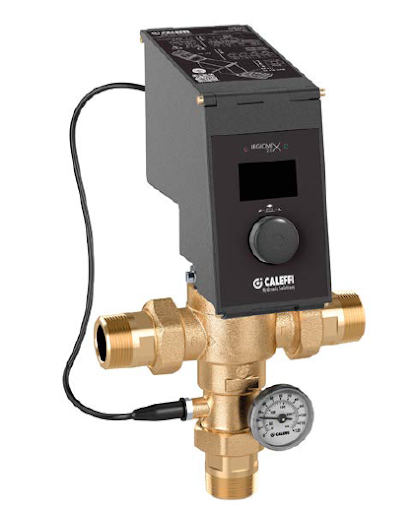
The electronic hybrid mixing valve combines the typical function of the mechanical thermostatic mixing valve and the management efficiency of an electronic mixing valve in a single device.
The thermostatic mixing valve uses the mechanical action performed by the internal control thermostatic element, which responds promptly to any variation in temperature, pressure, and inlet flow rate to quickly restore the mixed water temperature value at the outlet.
This standard mixing valve is effectively handled by a motorised actuator that, upon the signal coming from the temperature probes and under the control of a specific regulator, changes the mixed water temperature set position.
The electronic regulator, directly on the actuator, allows the mixed water temperature control according to different functional programs, both for normal control and for the thermal disinfection for the prevention of Legionella.
An optional memory system allows recording of every minute of flow temperature, return temperature, alarm, and functional statuses, useful for monitoring the operating status of the entire system.
Appropriate relays are used to manage the alarms and external appliances, for example for loading accumulation hot water and the switching on/off recirculation pumps.
The regulator is fitted for remote control with specific transmission protocols such as MODBUS, through optional board, for use in Building Management Systems (BMS)
So, in a nutshell we need to join the 4th Industrial Revolution and to start using current day technology available to us so that we can ensure our own and others safety.
For any further information on this product please feel free to contact the writer.
Q:How do I do fault finding on my PCV without removing it from the system?
A: Often the Pressure Control Valve is replaced unnecessarily. Manufacturers often get the complaint that the valve worked for many years and then started leaking, however the new valve started to leak within days of being fitted. So why are the new valves not as reliable as the old ones?
Simply put they are just as reliable. In most cases the old valve should not have been removed as it was not faulty. When the valve starts to leak and it is old we automatically, and incorrectly, assume that the valve has come to the end of its life. By doing some simple tests we can ascertain what the cause of the leak is.
Before doing anything with tools we need to eliminate normal expansion as the cause. The expansion relief valve only discharges water when the system pressure reaches the rated pressure. This could be because of expansion. To eliminate this, turn off the electricity supply to the geyser. Water is not compressible so if it is leaking due to expansion it will stop dripping immediately. If it does stop dripping, we have confirmed that it is expansion. When doing this test make sure that there is no solar heater present as this will continue heating the geyser even if the element has been switched off.
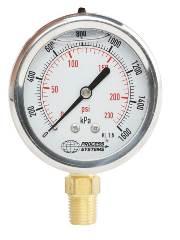
If the valve continues to drip, we need to determine what part of the valve is malfunctioning. The first piece of equipment that we require is the humble Pressure Gauge. Attach the gauge to any suitable point downstream (after) the control valve. Check the reading. Discharge some water from the system so that the water pressure returns to the valve’s set pressure. Take a reading. If the valve is at set pressure (see table attached) but the relief valve is still discharging, the relief valve part of the valve is malfunctioning.
If the valve immediately goes to the discharge pressure it is safe to assume that the port that stops the water pressure at the set pressure is not sealing off. (Before we open the valve make sure that the extra pressure is not coming from back pressure from an unbalanced feed. This would only be the case if new alterations to the system have taken place.)
Once you have ascertained where the fault lies you can decide what action should be taken. By having done these tests it will eliminate your customer phoning you and having to go back for a follow up inspection that you are not going to be paid for and is going to keep you from helping another customer. You will also gain your customers trust and respect for having done a professional analysis of the system.
Happy plumbing and keep safe.
Q:What type of check valve should I use?
A:There are two types of check valves, or as most people call it non-return valves. The first one is a swing type check valve. This valve is recognized by the fact that it has a free-swinging gate (flap) on the inside that seals when the weight of the water forces it closed. The sealing face of this device is normally perpendicular to the direction of the flow.
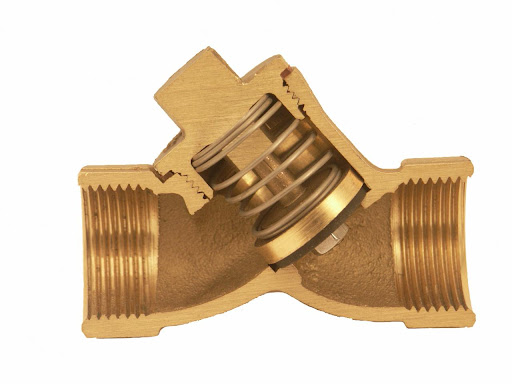
The other type of valve is a Spring Type Check valve. In this valve the sealing faces are forced together by a coil spring. When there is no flow and the force of the water on the seal is at balance the force of the spring will close the valve. A positive water flow is needed to open the seals from each other. This design is such that a very soft closing action is achieved and thus water hammer is seldom experienced. The one sealing surface is normally constructed from a neoprene type of material that enables easier sealing.
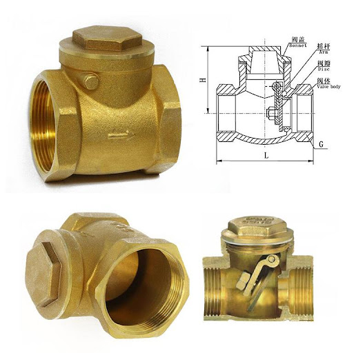
into account, it is obvious that only a Spring-Loaded Check Valve should be used for normal potable water installations. One of the drawbacks of the Spring-Loaded version is that it can’t handle very high temperatures. Swing type check valves can handle the heat but lack the capabilities that is required from a high heat type of installation like a solar heating system. There are however many different products that are specially designed to handle these requirements. For more information on alternative products contact your specialist valve manufacturers.
Q:How can I ensure that my geyser valve is still compliant after I have serviced it?
A:What makes a product compliant? There is a SANS manufacturing standard for most plumbing products. These standards prescribe a minimum performance standard, and they are tested and controlled by regular sample testing. When you procure one of these products you can be confident that it is going to perform according to the desired requirements.
So how do you know that when you have worked on one of these products it will still comply to these standards? When servicing or working on a product you must use original components when replacing any parts. You will also have to know what the prescribed performance standard is for the product that you are working on. If for instance you are working on a geyser valve you must test the valve for compliance before signing of on the job. So, you will have to check if the set pressure on the valve is within the desired parameters (for a 400Kpa valve, between 280 and 340Kpa). Next you must check if the relief function on the valve is working at the correct pressure (380 -400kPa).
To summarise, if you have used original replacement parts and the valve is performing within the correct parameters, you can rest assured that the product that you have worked on still complies.
Contact the manufacturer of the valves that you are using for more specific instructions relating to the product that you are using.
Q:What pressure rating should my PCV be if the installation is fed from a supply tank?
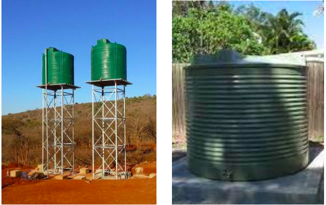
A:Before we can decide on the rating, there are a few things that we need to consider:
What is the purpose of a Pressure Control Valve? It is used to reduce the incoming mains pressure to a safe system pressure.
Is the tank at such a height that you are receiving pressures above 600 kPa? A tank 6 meters high will deliver 60kPa static pressure (roughly 10kPa per 1 meter head of water). If the pressure is below the maximum designed system pressure, you do not need to fit a PCV as the supply pressure cannot increase unless a pressure pump is added to the design. It is still a requirement to fit an Expansion Relief Valve at the geyser as a safeguard against any unplanned pressure spikes. You need to make sure that there is no flow control device such as a non-return valve between the geyser and the ERV.
Before changing anything on an existing tank fed system, it would be necessary for you to do a proper assessment of the system so that you do not compromise any built-in safety features.
Once again, the most crucial part of any design is the use of a Pressure Gauge and an accurate knowledge of the limitations of all the components that form part of the installation.
To summarise, if the pressure from the tank is such that it is below the maximum allowed design pressure you do not need a PCV.
Q:What is the difference between a PCV and a PRV?
A PCV is a “Pressure Control Valve” and a PRV is a “Pressure Reducing Valve”. So what does that mean?
A PRV only has a single function and that is to reduce the incoming water pressure. If for some reason the pressure in the system increases downstream the valve cannot react to this. In this instance an ERV (Expansion Relief Valve) needs to be fitted to the system to react to this situation.
A PRV only has two connection points.
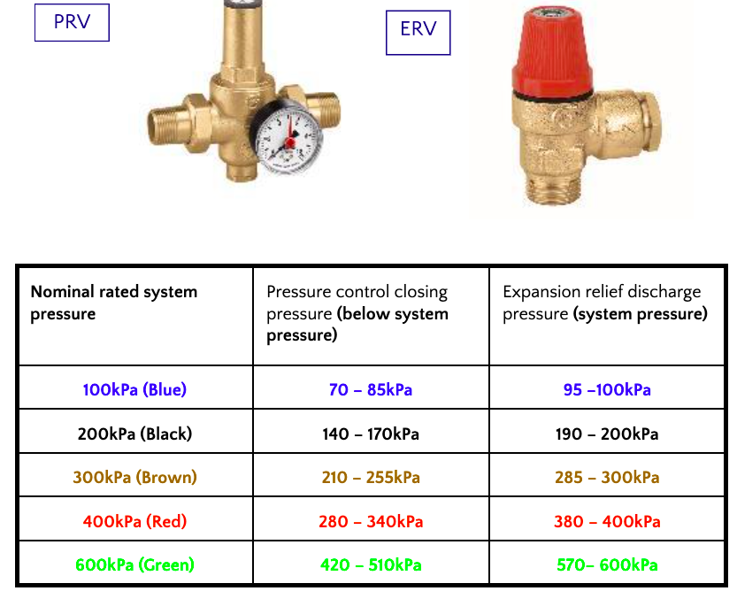
A PCV has a dual function 1) reduces the mains pressure to approximately 80% of the rated pressure of the valve 2) relieves any excess pressure that builds up downstream of the valve. There is a pressure gap of 20% between set and relief pressure. This enables the system to absorb some of the expansion pressure generated by the heating of the Hot Water Cylinder. The PCV normally has three connection points.

The PCV is the common one that is used in most domestic installations. You have to remember though that the position of the PCV is very important as you are not allowed to have an isolating valve or check valve between the Hot Water Cylinder (HWC) and the PCV as this will cut off the expansion function of the system. So, if you require the valve to be situated outside and have an isolation valve at the HWC an Expansion Relief Valve needs to be installed between the HWC and the isolating valve. In this way of installation it would be more cost effective to have a PRV outside the building and the ERV at the HWC. By doing the installation this way it makes any maintenance very convenient as you only isolate the HWC while the rest of the installation still remains commissioned.
Remember that SANS 10254 requires all HWC installations to have 2X Vacuum Breakers, a PRV, an ERV and a Temperature and Pressure Safety Valve.
I hope that this has cleared up any confusion that may have existed.
Q:Where and how should a RPZ valve be installed
If we refer to the legislation that calls for a RPZ valve it also specifies where and how it should be installed.
Let us start this discussion then by having a look at SANS 10252/1 2018, to see what the legal requirement is:
7.4.3 Prevention of backflow
7.4.3.1 Adequate measures shall be taken to prevent the back-siphonage of water into the
following:
b) an installation, in all cases where:
1) the design of terminal fittings installed (including any hose bibcock, laboratory taps or
movable shower units) is such that a hose or any other flexible pipe can be attached to the
fittings,
2) fire hose reels are installed in a combined installation,
3) an underground irrigation system can provide contact between polluted water and water
within the installation, or
4) any other fittings can provide contact between polluted water and water within the
installation.
Here it clearly states that any installation that has a tap where a hose can be connected, or where the system can in any way make contact between polluted water and the potable supply, a backflow prevention device should be installed. The type of device applicable is also outlined in Table 12.

Here it gives us two different types of equipment that can possibly be used. SANS however continues and states in point 8.4.2:
8.4.2 Backflow prevention devices
8.4.2.1 Any backflow prevention device shall be installed in such a position that
a) it can be readily inspected,
b) a condition of backflow in the pipe in which the device is installed can be readily detected,
c) it is readily accessible for removal for the purposes of servicing, repair, or replacement, without
alteration to the water installation or to the structure within which the device is situated,
d) it cannot be flooded by water or any other liquid, and
e) in the case of a vacuum breaker, it is installed in an appropriate anti-syphon loop.
8.4.2.2 Any additional installation instructions issued by the manufacturer or supplier of non-return
valves shall be complied with.
Whatever backflow prevention device is used it must indicate when there is any backflow taking place. Therefore, only a Reduced Pressure Zone backflow preventer can be used, as a double check valve type does not make provision for a visual indication of backflow.
This is then the why, but what about the how and where?
The valve should be installed in such a way that the whole installation is covered, this would mean installing the RPZ Valve just after the Water Meter. If necessary, you may need to protect your own installation from backflow from toxic zones within the installation. The bottom of the outlet from the valve must be above the level of any possible ponding to prevent any discharged water from being sucked back into the system.

You may be concerned by the crime factor in the area where the valve is installed. If this is the case, you may enclose the installation in a brick or concrete surround. Provision must however still be made for a visual indication of any backflow via an outlet in the bottom of the surround.

You will note that the drawings requires that there be an isolating valve (Ball Cock) situated before and after the RPZ Valve. You will also need to fit a suitable strainer between the upstream Ball Cock and the RPZ valve.
Backflow prevention can be a very daunting topic, however, if you follow the guidelines set out in SANS10242/1 all your installations will be a success story.
For more information feel free to contact the writer.
Q:Am I allowed to install a PCV upside down?
How do I know what is the top or bottom of the valve as there are no markings indicating top or bottom of the unit?
To decide what is the top or bottom of the valve we need to understand what the requirements in SANS 10254 is.SANS 10254 point 5.2 says:
5.2 Discharge from valves
The discharge pipes from expansion control and safety valves shall
c) be so installed that
1) they incline downwards
continuously to their outlet,
7) water traps which could prevent the free return of air into the system do not develop,
So what does that mean? If we look at the design of the valve we will notice that the Expansion Relief Valve always protrudes perpendicular to the rest of the valve.
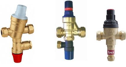
The physical workings of the valve does not get affected by the position of the Expansion port. However if we install the valve with the Expansion port to the top we will be allowing some water to be trapped by nature of the installation. This would be in contavension of the SANS’s requirements that requires for a continuous downward slope from the valve to the end of the discharge pipe. The water trapped in this area could also prevent the free flow of air back into the system.
In almost all of the installations that I have seen the valve has been incorrectly installed. By turning the valve to face the correct way will not complicate the installation in any way. All that it requires is that we educate the installers that work for us of this requirement.
For further information regarding this, feel free to contact your local IOPSA technical advisor or the manufacturer of your product of choice.
Enjoy your plumbing.
Q:How does the dirt get past the strainer of the Pressure Control valve?
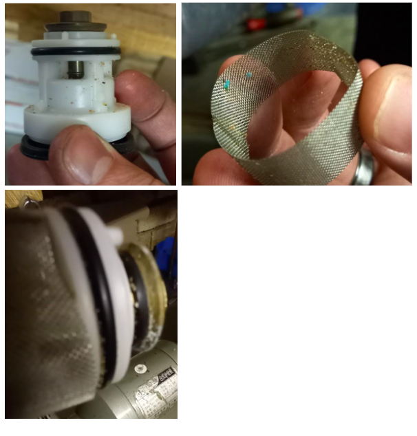
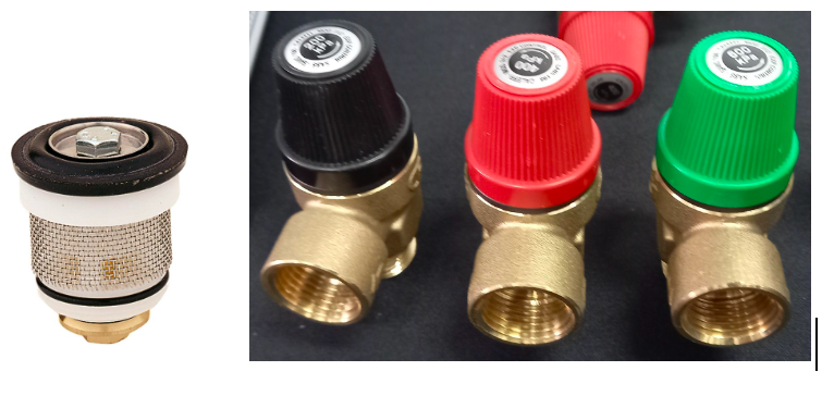
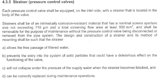
The plumbing system must always be protected from dirt entering the system. This is usually done by fitting an inline strainer, with a mesh size not bigger that 710µm, at the beginning of the line. As a secondary/ backup to the inline strainer the design of the Pressure Control Valve has to incorporate a strainer that is part of the valve. (see below)
So, with all this protection how does dirt get past the strainers?
If there is dirt on the downstream side of the valve, you will always find that it is an unballanced pressure system. You will also find that the cold water line has not been protected by an inline strainer and that the only protection that the system has is the strainer that is incorporated into the PCV. When a mixer is opened, the hot and cold water come into contact with each other. The stronger pressure of the cold water will over power that of the hot water and push the hot water back towards the PCV. This will simmultaniously carry dirt from the cold water line and deposits it inside the valve. The effect of unbalanced pressure on a system is more obvious currently due to the use of water saving fittings being used (don’t remove these fittings, fix the system).
So, when a valve malfuctions due to dirt in the valve, it is not because the valve has failed, but rather due to the installation not complying to the proper criteria for this type of installation.
I say type of installation because: If no mixer is present in the installation the effect of an unballanced installation will not have the same result. The installation will however still not comply with the criteria stippulated by law. So next time you find dirt inside the valve, first fix the cause(Balance the system) and then proceed to clean the valve. If we don’t do this the home owner will not receive the proper customer satisfaction and will keep calling you back to fix “your” problem.
